Modeling in Houdini using VDB SDF volumes

Tutorial / 14 May 2023

I noticed that people Modeler for Houdini Discord group were interested in SDF boolean operations, so I decided to create a simple example of SDF usage and share some of my notes.

There are two versions of the same example file:

VDB_SDF_Modeling.hiplc - The original file, but it contains nodes from Modeler 2023.4 plugin.

VDB_SDF_Modeling_Stashed.hiplc - A copy of the first file in which I replaced all operations from the Modeler 2023.4 plugin with Stash nodes.

If you do not have Modeler plugin, then download the second file and you will still get an idea of boolean operations using SDF volumes.


The file contains examples of using the following nodes and operations:

VDB from Polygons (to convert polygonal geometry to SDF volume).

VDB Smooth SDF (to smooth edges of geometry similar to the results from polygonal round bevel).

VDB Resample (to change voxel density to increase object detail).

VDB Combine (to apply boolean operations: SDF Union, SDF Difference, SDF Intersection).

VDB Reshape SDF (to expand or narrow voxel shapes, similar to the Peak operation).

VDB Convert (to convert SDF into polygonal geometry).

Volume Deform (to deform voxel shapes by using Lattice from Volume node in conjunction with Bend node to deform point grid which represents voxel grid).

Name and Attribute Edit String (to build hierarchy of LOP primitives while working in SOP)


Notes about using SDF nodes:

  1. Increase voxel density only when necessary. Generally, I used a voxel size of 0.02 when converting geometry through VDB to Polygons and could move shapes interactivly. However, in some cases, I needed narrower or smaller bevels and increased density to 0.01 voxel per unit in exchange to performance.
  2. After all operations, you can also increase voxel density through VDB Resample to get a denser and more detailed polygonal mesh from Convert VDB.
  3. Use different smoothing modes to maintain performance. Instead of increasing the number of smoothing iterations in VDB Smooth SDF, try to change the type of operation: Mean Value for normal smoothing, Gaussian for strong smoothing, Mean Curvature Flow for weak smoothing or smoothing small details.
  4. If you need to place one object inside another, for example a button in a housing, use VDB Reshape SDF to expand the SDF before boolean subtraction.
  5. I didn't find a way to store color in SDF and pass it through boolean operations, so after converting to polygons by Convert VDB I used Bounding Volume parameter in Group node to select the area that I want to color using SDF volume.
  6. Deform objects in voxels through Volume deform instead of deforming them in polygons. This is convenient because the bend deformer when used on polygons will not be able to bend the area where not enough geometry, but through Volume deform, you bend a point grid, so you can bend and deform even each pair of voxels.

Notes on modeling in SOPs within LOPs:

  1. To improve performance, prevent SOP from the constant transferring of data to LOPs. To do this, place Output node inside the SOP and connect the geometry to it only when you want to transfer it to the LOP, otherwise keep geometry disconnected.
  2. The same goes for working inside Component Geometry node: connect geometry to the default, proxy, and simproxy output nodes only when necessary, otherwise, the entire node tree will be recalculated with every change.
  3. Start building hierarchy of LOP primitives while still in SOPs. Hierarchy construction will occur from top to bottom, from leaf to root. At the very beginning (for leaves), add Name node that will create the corresponding attribute and enter the geometry name into it, for example, Mesh. Then add an Attribute Edit String node, specify that you want to edit Name attribute, and in Editor tab, set "*" (all existing names) in From parameter. To the To parameter add the name of the LOP primitive where you want to place the geometry, like "Primitive/*". Thus, the Name attribute will become "Primitive/Mesh". Further, continue to add Attribute Edit String nodes with the same parameters to assign more parents or to group primitives after merging. The last Attribute Edit String will have "/*" name set in To parameter and will close the path (for example, "/Gamepad/Triggers/Primitive1/Mesh").

I've used the video as reference for the model.

KineFX Ball for Houdini: Animation Rig and Geometry (HDALC)

Article / 13 May 2023

I made the rig for practice in animation and as example for how to make a squash and stretch constraint using KineFX in Houdini.

It consists of 3 nodes:
1. KineFX Ball Geometry (optional) node contains set of 6 pre-cached geometry presets for different types of balls: Tennis, Golf, Soccer, Volleyball, Basketball and Toy.
You can replace this node with any geometry that should be placed on the ground and be 1 unit in height.
Or don't use anything at all because next node contains a simple test sphere inside.

2. KineFX Ball Rig contains skeleton rig for a ball, controllers and shape library for them. You can change appearance of those shapes by diving inside the node and adjust Attach controls node's parameters.
3. KineFX Ball Animation gives you access to Rig Pose state for animating in viewport and set of parameters for precise control. The node also contains logic for calculating squash and stretch deformations of rig and Joint Deform to output final deformed(animated) geometry.

How to install:
1. Download these HDA files from the github repo:
FaitelTech.KineFX_Ball_Geometry.1.0.hdalc
FaitelTech.KineFX_Ball_Rig.1.0.hdalc
FaitelTech.KineFX_Ball_Animation.1.0.hdalc
2. Install them either through Houdini: File - Import - Houdini Digital Asset or copy them to the Houdini preferences folder (Documents/Houdini 19.5 on windows) - otls.
3. In SOP context in Houdini press TAB and type: KineFX Ball

FAQ:
How to animate a ball?
- The rig made and inspired to be used along with the tutorials for Maya:
FREE Ball Animation Rig for Maya
Simple Ball Bounce Animation Tutorial
Ball Bouncing Along Animation Tutorial in Maya - PART 2
But how to do the same in Houdini?
If you don't familiar with Houdini's animation editor watch the series:
Houdini Animation Editor 101 - Part I 
Houdini Animation Editor 101 - Part II
How do I reset the animation?
In KineFX Ball Animation node right click on any parameter or parameters tab (Ball Animation tab for example) - Delete Channels, Revert to default.


Compile OpenCV with CUDA support for Python in Houdini on Windows 11

Tutorial / 08 May 2023

With the recent release of MLOPS for Houdini, I've got interested in Python libraries for image processing. One such library is OpenCV. The pip-installable version of OpenCV mostly runs on CPU and uses OpenCL to accelerate some functions. However, to accelerate features like tracking and image warping, it is necessary to compile OpenCV with CUDA support. 

I recommend to not skip any steps in this article because it can lead to compilation errors or problems with installing the compiled package. I've tried to shortcut on every step, so believe me :)

To start with, I'll briefly list what we'll need:

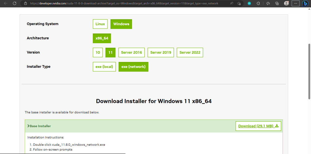
1. Installing the CUDA Toolkit

CUDA allows software to use graphic card from Nvidia for data processing. 

Download and install the CUDA Toolkit on your PC with an NVIDIA graphics card. I will be using CUDA 11.8 because this version is used by the MLOPS nodes at the time of writing this article. Use Express settings during installation, we're going to install cuDNN to folder of CUDA installation next.

2. Installing cuDNN. 

CuDNN is a GPU-accelerated library for deep neural networks. 

OpenCV supports DNN, so we need to install it to compile the package successfully. 

To download cuDNN, you will need to register and sign in on https://developer.nvidia.com website.

During registration, if you are not associated with any organization, then in the mandatory field "Organization name", specify "Individual". 

Click on Download cuDNN v8.9.1 (May 5th, 2023), for CUDA 11.x , then Local Installer for Windows (Zip)

Download archive to any folder for example, C:\Users\Aleksandr\Documents\Sources\  

Unpack and open the folder: ex. C:\Users\Aleksandr\Documents\Sources\cudnn-windows-x86_64-8.9.1.23_cuda11-archive\cudnn-windows-x86_64-8.9.1.23_cuda11-archive

To install cuDNN, you need to select and copy the bin, include, lib folders from downloaded cuDNN directory to the directory where CUDA Toolkit is installed: C:\Program Files\NVIDIA GPU Computing Toolkit\CUDA\v11.8 by default. Copy all three folders with replacement.

Copy and replace bin,include,lib folders from cuDNN to root of CUDA/v11.8 folder.

3. Installing Visual Studio

OpenCV sources are written in C++, and we need Visual Studio software to compile them into python package.

Download Visual Studio Community 2022 version. 

Run VisualStudioSetup, after which the Visual Studio Installer will open. Here we should select all the necessary components.

First, we need to check "Desktop development with C++", 

and on the right, we will need the following optional components: 

  • MSVC v143 - VC 2022 C++ x64/x86 building tools
  • C++ ATL for the latest v143 build tools
  • Windows 11 SDK
  • Just-in-time debugger
  • C++ Profiler tools
  • C++ CMake tools for Windows
  • C++ Address Sanitizer

Second, we need "Python Development":

  • Python 3 (64-bit), 
  • Python Native development tools, 

This way we install Python inside Visual Studio and guarantee the creation of an OpenCV package in it at the very end of this article. 

Press Install.

3. Installing Numpy.

NumPy is python dependency which is often used in combination with OpenCV to manipulate and process images and videos efficiently. We need it to build OpenCV.

Open Command Prompt in Windows 11: 

Press Start - Type "CMD" - Command Prompt

Install Numpy through pip Python's package manager:

Type: py -m pip install numpy

Press Enter

On this screenshot NumPy is already installed to Python in Visual Studio folder

4. Install CMake

CMake automates the generation of build files for various platforms. We need it to generate Visual Studio project files from downloaded OpenCV sources.

Download Cmake and install it in default location.

Windows x64 Installer: cmake-3.26.3-windows-x86_64.msi

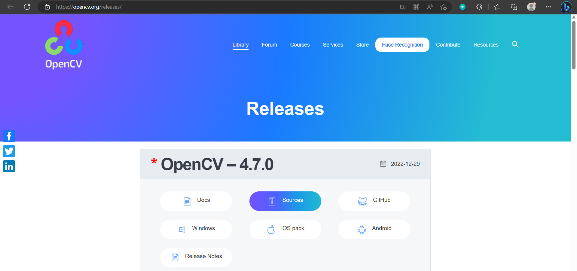
5. Download OpenCV sources

This is an original source code of the OpenCV project.

Download and unpack the OpenCV source files into any folder, for example: C:\Users\Aleksandr\Documents\Sources\opencv-4.7.0.

OpenCV-4.7.0 - Sources

6. Download OpenCV-contrib files

OpenCV-contrib is a repository of additional modules and extensions for the OpenCV. We're going to get CUDA modules from it.

Download OpenCV-contrib files and unpack it into any folder, for example: C:\Users\Aleksandr\Documents\Sources\opencv_contrib-4.7.0

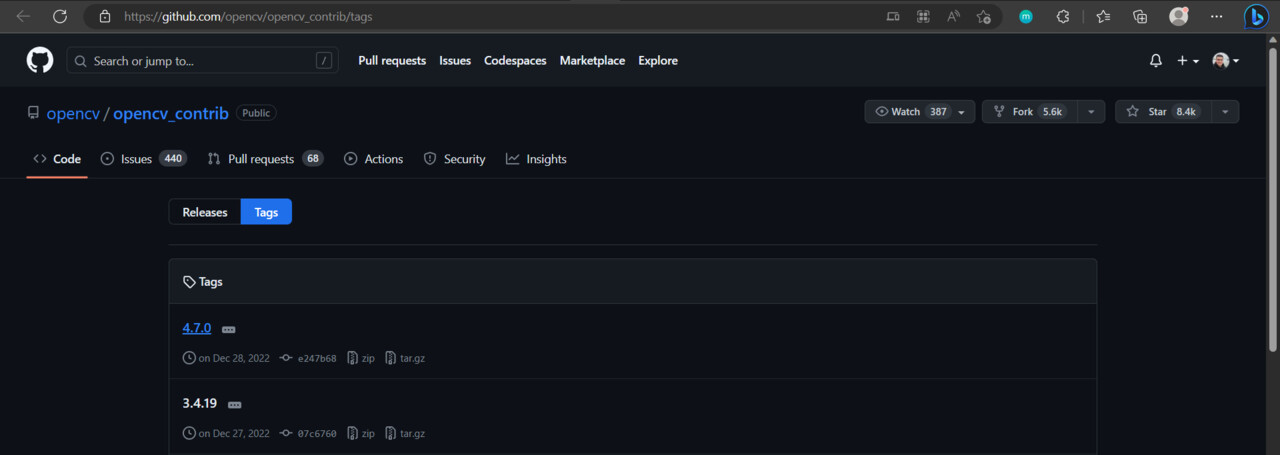
GitHub - OpenCV/OpenCV_contrib - Tags - 4.7.0

7. Create Build folder

We need some folder to Cmake generate project files into.

Create empty folder "Build" where we're going to store opencv project files for building. For ex. C:\Users\Aleksandr\Documents\Sources\Build


8. Run Cmake

Press Start - run CMake

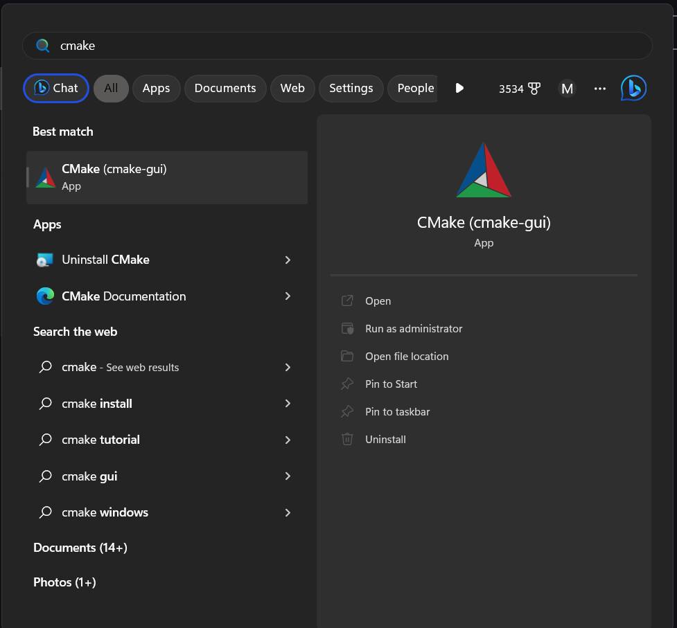
After that, the CMake window will open, where we will prepare the Visual Studio project for launch:

In "Where is the source code" press "browse source" button and select folder where we extracted opencv source code previously. For ex. C:\Users\Aleksandr\Documents\Sources\opencv-4.7.0

In "Where to build the binaries" press "browse build" and select Build folder which we created previously. For ex. C:\Users\Aleksandr\Documents\Sources\Build

Press Configure button.

Configure window - Optional platform for generation - select x64 - Press Finish

Type the next variables in the search field:

WITH_CUDA : Check
ENABLE_FAST_MATH : Check
BUILD_OPENEXR : Check
BUILD_opencv_world : Check

Also, we need to set path to folder where additional OpenCV modules (opencv_contrib-4.7.0\modules) are stored:

OPENCV_EXTRA_MODULES_PATH : C:/Users/Aleksandr/Documents/Sources/opencv_contrib-4.7.0/opencv_contrib-4.7.0/modules

Press Configure button again.

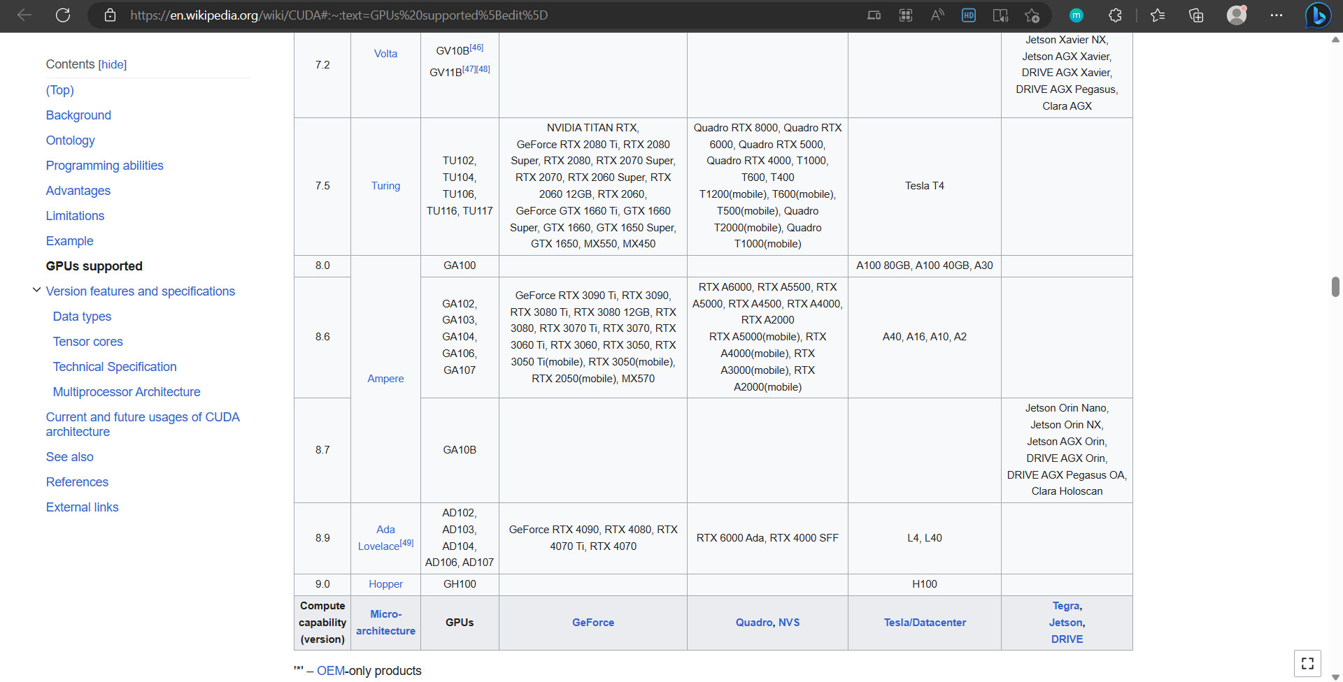
Now we can configure CUDA module variables:

CUDA_FAST_MATH : Check

Here you need to check Compute capability (version) specific for your graphic card. For example: I have a graphic card Nvidia RTX 3060 and its compute capability version is 8.6


CUDA_ARCH_BIN : 8.6

We don't need to debug project, so change the next variable to Release only:


CMAKE_CONFIGURATION_TYPES : Release

Press Configure.

Press Generate.

Press Open Project.


After that, there will be a configuration and the first launch of Visual Studio, and the OpenCV project will open, which we will compile.

9. Build and Install OpenCV in Visual Studio


When Visual Studio and the project open, in the right-hand window Solution Explorer, expand the CMakeTargets tab.

In the tab Right Click on ALL_BUILD - press BUILD

Wait, this building process may take a long time.

Next, Right Click on INSTALL - press BUILD

The result of the installation is a new cv2 folder in the Python directory of Visual Studio:

C:\Program Files (x86)\Microsoft Visual Studio\Shared\Python39_64\Lib\site-packages\cv2

10. Copy and check OpenCV package in Houdini

Now we need to copy the OpenCV package to the directory where Houdini's hython can find it.

If you are not using MLOPs, it can be a directory in your Houdini user preferences: C:\Users\Aleksandr\Documents\houdini19.5\scripts\python 

If you are using MLOPs, go to the folder where you store MLOPs data: $MLOPS/data/dependencies/python, for example: C:\Users\Aleksandr\Documents\GitHub\MLOPs\data\dependencies\python. Then backup copy of the cv2 folder to any location and delete it. 

Copy cv2 folder from C:\Program Files (x86)\Microsoft Visual Studio\Shared\Python39_64\Lib\site-packages to target directory. 

Launch Houdini.

Open Windows - Python Source Editor

Type the code:

import cv2

count = cv2.cuda.getCudaEnabledDeviceCount()

print(count)

This code will output to the console the number of devices that support CUDA computations.

 If this number is greater than 0, for example 1, it means that you have successfully installed OpenCV with CUDA support in Houdini.

Related articles: 

How to build OpenCV with Cuda and cuDNN support in Windows – 2023

Quick and Easy OpenCV Python Installation with Cuda GPU in Under 10 Minutes

Digital Human Contest 2020 - Facial Hair

Making Of / 18 November 2020

When I was looking for how to do a hair, I found the stream record where Arvid Schneider very clearly showed how to make hair using the Groombear  plugin for Houdini. The plugin seemed great to me and very convenient, but nevertheless, the overall style of work remained the same: to put a guide for the hair, you need to change the direction of the viewport's camera a lot and often, to see guide's position in three- dimensional space. Then I remembered that the most convenient thing I've seen for working with curves is the Gravity Sketch

Despite the fact that VR is still in the early stages of its development, I always have fun sketching in three-dimensional space, especially it’s convenient to manage rigs and mannequins, as well as work with complex shapes of curves, plus references could be placed anywhere and in any size.

Because of inexperience, I overdid a little bit (a lot!) with the density of the guides.

When exporting curves from Gravity Sketch there were two difficulties, the first is that the curves were three-dimensional geometry, and the second is that unlike GroomBear, the curves in Sketch Gravity fall under a geometry.

So, I've made a prototype in Houdini that turns gravity Sketch's cylindrical tubes into curves, and removes parts of the curves that are inside the mesh.

Experimentally, I found out that all the cylindrical curves in the gravity sketch consist of 12 corners, which I fused (weld) to one point.

Note: In the future, I can complete an algorithm that would save the diameter of the cylinder before flattening and write it down as a width parameter for guides to GroomBear, thus achieving a complete external matching of curves from Gravity Sketch and GroomBear.

Curves that got inside the mesh, I easily removed, thanks to the solution proposed by Petz on odforce.net.  Thank you, Petz!


//run over Primitives


int points[] = primpoints(0, @primnum);
int point_end = points[-1];
int point_next = points[1];


vector hit_pos, hit_uv;
vector ray_origin = point(0, "P", points[0]);
vector ray_dir = point(0, "P", points[1]) - ray_origin;
int count = 0;


int cond = inpointgroup(geoself(), "_inside_", points[0]);
int curve = addprim(geoself(), "polyline", points[0]);
setprimgroup(geoself(), "inside", curve, cond, "set");


int i = 1;
do
{
    int prim = intersect(1, ray_origin, ray_dir, hit_pos, hit_uv);
    if(prim == -1)
    {
        point_next = points[i];
        addvertex(geoself(), curve, point_next);
        ray_origin = point(0, "P", points[i++]);
        ray_dir = point(0, "P", points[i]) - ray_origin;
    }
    
    else
    {
        count += 1;
        point_next = addpoint(geoself(), hit_pos);
        addvertex(geoself(), curve, point_next);
        curve = addprim(geoself(), "polyline", point_next);
        if(!cond)
            setprimgroup(geoself(), "inside", curve, count % 2, "set");
        ray_dir = point(0, "P", points[i]) - hit_pos;
        ray_origin = hit_pos + normalize(ray_dir) * 0.001;
    }
}
while(point_next != point_end);
removeprim(geoself(), @primnum, 0);

Because the result is ordinary curves, GroomBear easily converted them into guides.

Then I drew the attributes where the hair will grow.

And moved the eyebrows by looking on a reference photo through Pureref, it is more convenient to do it in Houdini rather than in Gravity Sketch, because the roots of the hair are tied to the mesh.

When I was generating hair, I basically added four effects from Hair Tools shelf in different proportions: Clump, Frizz, Bend, Lift.

In the Hair Utils panel in Houdini, there are Generate Hair Cards and Hair Card Texture buttons, by using them I've transformed my hair into cards and baked color textures. I did it very intuitively and will try to better understand this feature in the near future.

The submission date for the contest is already over, but I want to work in more detail with the hair and their binding to the face of the head, as well as try to make dreadlocks with complex weaving, where all possibilities of Sketch Gravity VR will be revealed in full.


Digital Human Contest 2020 - Iris texture

Making Of / 18 November 2020

Eye shader in Character Creator is pretty versatile, but there was two moments, I wanted to be sure that iris pattern is accurate and to desaturate sclera a bit.

To generate iris texture I've bought HumanEyes Iris #100 on Texturing.xyz.

Following the Standard workflow tutorial, I've imported Low_poly iris base from pack and subdivided it four times.

I decided to work with textures directly on geometry, not in a shader, so I projected iris displacement map to color attribute

Then displaced it inside vex operator (kind of visual coding network), 

Same way as displacement I projected color information.

As I've mentioned at a beginning, Character creator 3 has base eye with uv that why I imported its eye texture and put it on a plane, then I adjusted iris position to iris on the plane and baked it out.

Thank you for reading and see you in the next chapters.

Digital Human Contest 2020 - Texture transfer

Making Of / 12 November 2020

Houdini provides users with a wide range of functional blocks (nodes) with which you can build up logical schemes of any complexity to work with computer graphics.

My follow-up work is based on the analysis, formalization and straight repetition of a tutorials presented on texturing.xyz. I relied most on “Sefki Ibrahim - Realtime Digital Double with Character Creator and TexturingXYZ” and “Pietro Berto / Making of Emmanuel”.

I want to say thanks to the authors for their incredible work and clear demonstration of their workflow.

Step 1. Texture projection on mesh

I imported the character directly from Character Creator through GoZ import node. Removed the eyelashes and subdivided the mesh several times.

Then created and put on against the face a plane and set its proportions to same as in purchased photo of scanned skin.

Then marked the corresponding points between the scan and the mesh in the Topo Transfer node. 

Started the projecting process.

Step 1.1. Fixing the projected plane

When projecting is done, not all areas usually lay as they should, especially on the ear tips an earlobe, as well as nostrils. 

I hand-adjusted my ears and nose with the Push Tool (similar to the Move brush in zbrush) from the Modeler plugin for Houdini.

Then smoothed out in projection mode the problem areas through the nod of Topobuild retopology.

Step 2. Baking textures.

The texturing.xyz’s set contains 3 different multichannel maps - Albedo (Skin Color), Displacement (Pores info), Utility (Additional info). I needed to bake them to UV coordinates of my character. I took one of the SideFX Labs nodes called Simple baker and used a mesh which I transferred earlier from GoZ as a target geometry, and put projected plane as baking source, which I can use to lay textures for baking.


Step 2.1. A bit of automatization.

I won’t to bake textures manually one by one, plus baking high-resolution textures takes a long time, so I decided to delegate some work to Houdini, because Houdini has blocks for tasks automation (PDG or TOP nodes). I created a scheme which tells Houdini that I need to accomplish three times a typical task: 

1.    Change the input texture via a switch with number of current task.

2.    Change the name of the map to import (original texture). 

3.    Change the name of the map to export (processed texture). 

4.    Bake the texture. 

Now I can bake several textures at once with the touch of a button. 

Step 3. Textures mixing.

Since the textures used for baking covered only part of the face, they lack information about other parts of the mesh. I’ve used default base mesh maps to get missing info. 

For mixing I used two masks: 

The first I painted the color in the viewport right on the mesh with Paint node and transferred this information to the UV. 

I figured out how to do this by the examples by Symek and Hughspeers from Odforce.net forum. Thank you, guys. 

vector uv  = set(X,Y,0);
string path = "op:" + opfullpath('../../Baked_Texture_Tweaking/invert_color');
vector clr = uvsample(path, "Cd", "uv", uv);
R = clr.x;
G = clr.y;
B = clr.z;

I drew the second mask right on top of the UV coordinates through Rotoshape compositing node. Then I blurred the contours of the masks and combined it together with previous one. 

In the further I continued to process the images adhering to this non-destructive approach.

Note: at this step I made several mistakes that I tried not to repeat in the next.

1.    I didn't input the original image to Rotoshape, so this mask doesn't scale and only works with maps in 8k resolution, and it doesn't show up correctly on the node previews. 

2.    I didn't use proxy images to speed up work. In the current state Houdini’s compositing nodes doesn’t use the OpenCL library to speed up calculations with GPU, so working with high-resolution images becomes slow, but this issue is solved by using a proxy images with reduced resolution.

Step 3.1 A bit of automatization.

Repetition of step 2.5 only for textures mixing procedure. On the way out, I'll get 3 new temporary textures.

Step 4. Proxy images preparation.

To speed up further image processing, I generated copies of all the maps in ¼ ratio to the origin. And again, automated this process.

Step 5. Textures adjustments.

Throughout a textures there were many small places with extra information to be removed, such as eyelashes on the eyes, too dark nostrils, chin and insides of the ears. 

I used a mixing technique from step 3 but alternated sources to find good looking part of the skin for overlay, these were: 

1.    The map itself simply shifted by UV coordinates. 

2.    Original skin texture from texturing.xyz

3.    The map itself but mirrored. 

Then repeated all the operations for the rest of the maps through the task nodes. 

Step 5.1 Textures stretching.

During the baking process, the lips weren’t projected deep enough inside the mouth, to correct this I cut out the upper and lower lips and stretched them down and up accordingly with the Pin transform compositing node, then put them back on the source map and removed the extra info with a mask.

Step 5.2. Utility map adjustment

From the Utility map I needed information about the face front (for the roughness map), so I painted everything else black. And made a few small adjustments like in step 5. 

Step 6. Textures export.

I split utility maps and displacement maps by channels because each channel contains unique info about the skin and preserved as individual linear image.

Step 7. Roughness map creation. 

Character Creator allows you to flexibly adjust roughness for individual areas of the face, so I was required to create an average map with pores on the skin. To do this, I took the B channel from the utility card and inverted it, then multiplied it into an inverted channel R of displacement map. Then reduced the contrast and brightness. 

To be honest, I’m not satisfied with this method, I'd like to experiment with other ways of generating it in the future.

At this point, the preparation of the additional maps in Houdini was over, and I moved to Zbrush to mix the displacement maps, add details and bake them to a normal map. 

I imported the model from Character Creator through the GoZ again and subdivide the model to level 7. 

Then I created 3 layers for displacement maps and imported them one by one, adjusting the visibility of the layer by the eye.   

Addition layer was created for my own pores and wrinkles, which I was able to see on the references. My character is young, so he doesn't have a strong skin defects. There are some scars on the references but I didn’t sculpt them in order to don’t tie the character to a particular person. At the same time, I can add them later through SkinGen in Character Creator.

I’ve also added the micro skin by adding procedural noise and pushed it out in places where were no displacement maps, this noise is needed to smooth out the sharp transitions of displacement maps while working in Zbrush, but I did not baked it out, because Character Creator has its own micro-normal maps.

When I've done sculpting, I’ve baked and exported normal maps and moved to the eyes. 

I’ve also put the maps to SkinGen multiply layer for minimal checking.

Thanks for reading and see you in the next chapters.

Digital Human Contest 2020 - Head shape

Making Of / 12 November 2020

For the character I decided to use a real person as a guide and reference. I didn’t set myself a task to make a digital double, I just liked the appearance of the young guy which accidentally found. It turned out that the photos of this rap singer are all quite old, most of them dating back to 2007. I managed to find photos in a less decent quality on the photo stocks, but even on them it is difficult to see the small details


To begin with, it’s my first time encountering an anatomy of an African American man. In place where I live, there are many nationalities, but this particularly is uncommon and quite rare, I like learning and discovering new things, so I chose it as a challenge to myself.

I would like to note that the book - Anatomy of facial expression has given me a great help in studying anatomy of a head.


And from it, I learned that the shape of the African skull differs from the European, which in turn leads to a change in the size of the nose, the planting of the eyes, the position of the chin and many other quite significant characteristics.

I returned to the book occasionally, especially when sculpting different areas of the face tightly adjacent to the skull.

A couple of words about references. Already in the working process, I realized that it is necessary to collect not only high-quality references with a neutral expression (which I almost could not find), but also collect good photos taken at the various moments and at the craziest angles, such photos can help when, for example, some area is constantly in the shade or looks flat, but the camera takes an unusual angle and we can see it in full glory.

At the time of writing this post, I've used the following software:

Character Creator 3 

Zbrush 

Houdini 

The work begins in Character Creator by finding a basic mesh template that will be the easiest to shape in final character. 

As a base model, I chose the CC3+ African (who would've thought) from Character Creator’s the Basic anatomy set.


As a rule, in design it is recommended to move from large to small, from large primary forms to secondary and tertiary forms. The official Headshot plugin for Character Creator has an option “Active Sculpt Mode” that allows you to quickly switch between primary and secondary forms on the face and automatically display sliders to fine-tune your chosen area.  There are a lot of sliders in Headshot category of modify tab, so I often used keyword sorting like depth, scale, width, height, rotate, etc.

Note: Headshot adds its own facial morph sliders tab to the modify window, but standard sliders from the base model are still relevant and complement each other with headshot sliders.


On the rare occasions when I couldn't find the right slider or model complex round 3D forms, I’ve switched to Zbrush with GoZ. 

GoZ allows software to seamlessly share data in both directions at the touch of a button, I found it very convenient.  

Note: While modifying the mesh in Zbrush is preferably to be very carefully and try to follow the direction of topology of the base mesh to avoid stretches on UV coordinates and breakdown of topology guides for blend shapes with expressions.

Also, Character Creator have a flexible PBR Shader, with its help I adjusted the color of the skin to more conform to the reference while modeling. I also had to disable some of the default layer effects in the SkinGen editor because they didn't fit to my character's mood and age.

To have a little more control over the color in the Character Creator's viewport, I temporarily turned off all post-effects in Visual Settings.

While I was getting used to the workflow, I made about 20 unsuccessful versions of the character before I found the right direction.

After I achieved matching the shape of the face to the reference, I moved on to work on the texture of the skin.

To do this, I bought the images with scanned skin from Male 30s Multichannel Face #42 pack at texturing.xyz

For projection, editing and baking textures I used my main digital content creation tool - Houdini.